

|
Now that you are a whiz at Boolean math and understand the basics of AND, NOT, and OR - what in tarnation does that have to do with electronic components? Can you make a not gate out of resistors or something? Well, to put it simply - yes! Any kind of gate - including the ones we discussed (and some that we didn't), can be created using the discrete electronic components that we have learned already. Since we started with the NOT gate in Boolean math - it seems like a good place to start with in studying the schematics behind it. Years ago - they used relays to create logic circuits. This is not a far stretch of the imagination. If you apply voltage to a relay, it turns on. If you do not - it turns off. 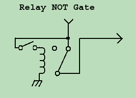 Let us first look at the NOT gate. Under its normal condition, 5 volts comes in on the top, through the switch part of the relay, and out to the right. If the toggle switch is flipped on the left side, the relay triggers, the coil pulls the relay switch in, and there is no output. 1¬→0, 0¬→1. We have created a NOT gate out of a relay. 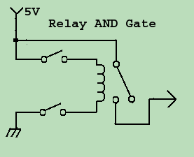 Now let's take a close look at the operation of the Relay AND gate. Again the 5 volt signal comes in from the top, and taking the path of least resistance, follows the road to nowhere! If we flip the top switch (SW1) we apply power to the coil, but because there is no ground, there is no complete circuit, and the relay does not energize. Again - the 5 volts goes nowhere. The same applies if we flip the bottom switch (SW2). It isn't until we flip BOTH SW1 AND SW2 that the relay energizes, and the 5 volts is allowed to continue on to the next circuit. 1∧1→1 else 0.... it is an AND gate. Now let's take a close look at the operation of the Relay AND gate. Again the 5 volt signal comes in from the top, and taking the path of least resistance, follows the road to nowhere! If we flip the top switch (SW1) we apply power to the coil, but because there is no ground, there is no complete circuit, and the relay does not energize. Again - the 5 volts goes nowhere. The same applies if we flip the bottom switch (SW2). It isn't until we flip BOTH SW1 AND SW2 that the relay energizes, and the 5 volts is allowed to continue on to the next circuit. 1∧1→1 else 0.... it is an AND gate.
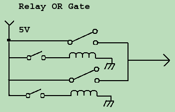 Now comes the all permitting OR gate. Following the signal, the 5 Volts comes in at the top, and moves its way to the right. It is stopped by the open relay switches, because neither relay is energized. If we close switch 1, relay 1 energizes and lets the voltage through. If we close switch 2, relay 2 energizes and allows current to flow through. If we close both switches, current flows, and again we have 5 volts at the output. 0∨1→1, 1∨0→1, 1∨1→1, 0∨0→0. We have an or gate. Now comes the all permitting OR gate. Following the signal, the 5 Volts comes in at the top, and moves its way to the right. It is stopped by the open relay switches, because neither relay is energized. If we close switch 1, relay 1 energizes and lets the voltage through. If we close switch 2, relay 2 energizes and allows current to flow through. If we close both switches, current flows, and again we have 5 volts at the output. 0∨1→1, 1∨0→1, 1∨1→1, 0∨0→0. We have an or gate.
Truth be told, relay logic is VERY old technology - predating the invention of the tube or transistor. However, evidence exists of its usefulness. I have run into many relay logic circuits in the repair of high voltage circuits. I've seen them implemented in industrial electronics, where they control motors, presses, and even the occasional air conditioning or security system unit. I have NEVER gone so far as Harry Porter did though - for your viewing enjoyment - meet the father of all relay computers!  At more than one point in the course - we discussed "class" of amplifiers, and terms like "saturation" and "cutoff". We went over these, because I knew then that you would be studying them in more detail now. Digital logic circuits, as opposed to analog circuits, NEVER run in class A, B, or C operation. Creating a clean, pristine, distortion free signal is not only not desired - it isn't possible. Wait a minute - the cable guy told me that when I went to DTV, I would have a perfect signal, and my TV looks better than ever now. Yes and no. It only "looks" better to you, because the massive amount of distortion you see, you don't see. It happens so quickly that it is beyond the frequency and range of your analog eyes to detect - but rest assured there is a TON of
distortion going on. I know this, because you are seeing the effects of "square waves", and there is no such thing as a perfect, distortionless square wave. We'll maybe cover all that in another course. At more than one point in the course - we discussed "class" of amplifiers, and terms like "saturation" and "cutoff". We went over these, because I knew then that you would be studying them in more detail now. Digital logic circuits, as opposed to analog circuits, NEVER run in class A, B, or C operation. Creating a clean, pristine, distortion free signal is not only not desired - it isn't possible. Wait a minute - the cable guy told me that when I went to DTV, I would have a perfect signal, and my TV looks better than ever now. Yes and no. It only "looks" better to you, because the massive amount of distortion you see, you don't see. It happens so quickly that it is beyond the frequency and range of your analog eyes to detect - but rest assured there is a TON of
distortion going on. I know this, because you are seeing the effects of "square waves", and there is no such thing as a perfect, distortionless square wave. We'll maybe cover all that in another course.
For now, suffice it to say that in Digital Logic circuits - there can only be 2 states - On, and Off (1 and 0). Those 2 states are represented in the electronic world as "saturation" and "cutoff". When a transistor (tube, FET or other amplifying device) is in saturation, it is so overly distorted that it can not go any higher no matter how much more signal is applied to the input. The opposite works for cutoff. The amplifying device has so little signal applied that it is completely turned off. Applying even less current will not make the output go any lower. Because the amplifier is set up to operate at such close parameters, (Class D, E, or even F), when you DO apply a nice sine wave (or Bethovan's 5th Symphony), to the input of the amplifier - it comes out as square shaped waves - with the tops and bottoms compressed off, and the sound coming out of it will be just plain hideous! However, if the signal you apply is already a distorted signal (saturated or cutoff), and you aren't worried about distorting it more - then it is just fine to push it through a class D, E, or F amplifier. Because of this - they use these classes of amplifiers in an effort to conserve energy. In Digital Logic, 5 volts is typically considered to be a 1, and zero volts (ground) is considered to be a 0. Typically, any input above 3 volts will send the transistor into saturation (making 5 volts output), and any input below 2 volts will put the transistor into cutoff (0 volt output). What happens if you apply a signal between 2 and 3 volts? Glad you asked. Because of the unstable nature of the circuit, any signal that falls between the saturation and cutoff points will cause the circuit to have unpredictable results - so we must at all cost avoid this situation. Often we run into this problem if a ground is not properly connected in a digital circuit, which is why grounding is so important in digital circuitry. 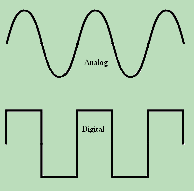 In an analog circuit, you would expect a sine wave, or similar analog signal to go through the circuitry. In a digital circuit, the signal looks much different, speeding through as a series of 1's (5 Volts) and zeros (0 Volts) over time. So the signals you would look for on an oscilloscope would look much different. The test equipment you need to troubleshoot it also looks different. Devices like logic probes, data and word analyzers, and computers are needed to decipher the presence and integrety of digital data. Simply keep in mind for now, as you move on to the next section of the course - that a 1 is 5 volts, and a 0 is well, 0 volts. In an analog circuit, you would expect a sine wave, or similar analog signal to go through the circuitry. In a digital circuit, the signal looks much different, speeding through as a series of 1's (5 Volts) and zeros (0 Volts) over time. So the signals you would look for on an oscilloscope would look much different. The test equipment you need to troubleshoot it also looks different. Devices like logic probes, data and word analyzers, and computers are needed to decipher the presence and integrety of digital data. Simply keep in mind for now, as you move on to the next section of the course - that a 1 is 5 volts, and a 0 is well, 0 volts.
|
| (On The Following Indicator... PURPLE will indicate your current location) | ||||||||||||||||||||||||
| 1 | 2 | 3 | 4 | 5 | 6 | 7 | 8 | 9 | 10 | 11 | 12 | 13 | 14 | 15 | 16 | 17 | 18 | 19 | 20 | 21 | 22 | 23 | 24 | 25 |
| 26 | 27 | 28 | 29 | 30 | 31 | 32 | 33 | 34 | 35 | 36 | 37 | 38 | 39 | 40 | 41 | 42 | 43 | 44 | 45 | 46 | 47 | 48 | 49 | 50 |
| 51 | 52 | 53 | 54 | 55 | 56 | 57 | 58 | 59 | 60 | 61 | 62 | 63 | 64 | 65 | 66 | 67 | 68 | 69 | 70 | 71 | 72 | 73 | 74 | 75 |
[COURSE INDEX] [ELECTRONICS GLOSSARY] [HOME]
| Otherwise - please click to visit an advertiser so they know you saw their ad! |
