

Lesson 53 - Amplifier Requirements and Block DiagramsThis is probably the biggest topic of them all. Electronics was limited to light bulbs and switches until the invention of the amplifier. At first, tubes were the only amplifiers on the market, until Walter Brattain utterd the immortal words, "This Thing's got Gain!" ushering in the new era of semiconductor based transistors. Gain was the key word in that sentence. Gain is the difference between a passive circuit, and an active one. The ability to amplify and even generate signals. It is because of gain that we can hear an intercom system, a telephone, a radio, and even see the faintest of stars in the universe. Gain means amplification, and amplification means making things bigger. A weak signal goes in, a strong one goes out. Gain. What a simple principle. Yet - it takes quite a bit to get gain. The stars have to be aligned just right. You've got to stand on the right foot, and hold your tongue in a certain position, and oh, yea, have a device capable of amplification, and apply the correct level of biasing voltages to it. Remember biasing? We discussed it when we were talking about Tubes. We again discussed it when we spoke of transistors. In the tube the plate has to be positive with respect to the cathode. In addition, it took quite a bit of potential difference between the plates to make it work. Even then, unless you had a cloud of electron witnesses hanging around the filiment, it wasn't going to happen. With the transistor, you needed to have a 7/10 of a Volt ( 0.7 Volts) difference between the emitter and the base before you could turn it on. Of course, the .7 Volts is assuming a silicon transistor. 2/10 of a volt was more in order if it was a Germanium transistor - well, you get the picture. In either case, amplifiers come in many styles and varieties, depending on what you plan on amplifying. There are voltage amplifiers, power amplifiers, current amplifiers, Class A, Class B, Class AB, Class C, Audio Amps, RF Amps, distribution amps, operational amps, and even limiting amps. I could most likely write an entire book just on amplifiers ( perhaps I will someday when my life gets put on hold ). But that is not the purpose of this course. THIS course is to explain things simply, and make the complicated understandable. Good luck with that. How am I doing so far? SOME explaination of amplifiers is in order at this point, though, so I'll do my best to keep it short, simple, and understandable. To begin with, all amplifiers need 3 things to work:
Let's now look at an "off the beaten path" topic - Block Diagrams. 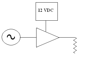 There are many different types of diagrams you'll run into while learning electronics. Mostly we've spoken of schematic diagrams and schematic symbols. Schematics (proper) will show every single component in the circuit. Sometimes that is overkill - information overload. What if all you want is a basic understanding of the circuit? That's where BLOCK DIAGRAMs come in. In a schematic diagram, a power supply is shown as a whole bunch of individual components. In a block diagram - it is just, well, a BLOCK! An Amplifer - on the other hand, is typically shown as a triangle, with the point going to the right (along with the direction of signal flow). As shown in our block diagram, the Amplifier (the triangle) is being fed with the signal from the signal souce (the circle with the sine wave in it). It has power coming from the 12 Volt power supply, and its output is going to a load. What is not shown here is whether the amplifier is a tube or transistor, what the values of the biasing resistors are, or even whether it is amplifying voltage, current, or power. In any case - it has gain. The gain is always some measurable amount, and if you compare the output signal on the right to the input signal coming from the left - the output should be some order of magnitude bigger. 
|
| (On The Following Indicator... PURPLE will indicate your current location) | ||||||||||||||||||||||||
| 1 | 2 | 3 | 4 | 5 | 6 | 7 | 8 | 9 | 10 | 11 | 12 | 13 | 14 | 15 | 16 | 17 | 18 | 19 | 20 | 21 | 22 | 23 | 24 | 25 |
| 26 | 27 | 28 | 29 | 30 | 31 | 32 | 33 | 34 | 35 | 36 | 37 | 38 | 39 | 40 | 41 | 42 | 43 | 44 | 45 | 46 | 47 | 48 | 49 | 50 |
| 51 | 52 | 53 | 54 | 55 | 56 | 57 | 58 | 59 | 60 | 61 | 62 | 63 | 64 | 65 | 66 | 67 | 68 | 69 | 70 | 71 | 72 | 73 | 74 | 75 |
[COURSE INDEX] [ELECTRONICS GLOSSARY] [HOME]
| Otherwise - please click to visit an advertiser so they know you saw their ad! |
