

Lesson 54 - Amplifier Classes
Amplifier circuits are "classified" by how accurately they reproduce the incoming signal. The classes, simply put, are A, B, AB and C for analog circuitry, and classes D and E/F for digital/switching circuits. First we will give you a brief overview, then cover each in more detail:
The class of operation of an amplifier describes how well it works, how efficient it is in power consumption, and how good the fidelity of the outgoing signal is. Let's take a look at the 3 most common classes of operation, and determine what makes them work the way they do. Class A Amplifiers: In a class A amplifier, the output signal is as pure as possible. The output is a perfect representation of the input signal. If a perfect sine wave is fed into the amplifier, a perfect sine wave comes out the output. When this happens, we say that there is very little Distortion, and that the amplifier has High Fidelity. High fidelity is important in systems such as stereos and video circuits. 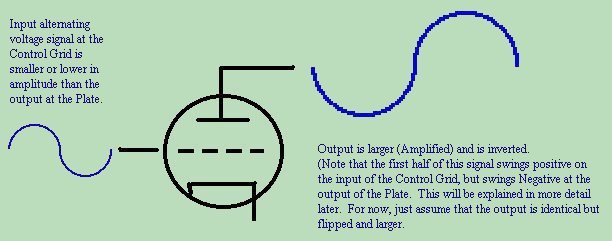 Class of amplification, is accomplished as a result of choosing the correct Quiescent Operating Point. Operating Point refers to the voltages applied to a circuit. Quiescent means at rest. So the Quiescent Operating Point is the voltages applied to the amplifier circuit before any video, audio, radio, or data signals are applied. By the way - some more terminology here: Baseband, IF, RF When creating radio waves, the frequencies are much higher than audio, video, etc. We call these Radio Frequencies or RF. Because we have so many different kinds of signals that can be applied to a radio carrier (audio, video, data, etc), we tend to lump them all together, and call them baseband signals. Sometimes it is to our advantage to use some intermediate frequency between the baseband and radio frequency signals when we are upconverting the frequency. These are called Intermediate Frequency or IF signals. This is just a heads up, as you will over time come across references to baseband, IF, and RF signals, and will need to have a rough idea of what is being talked about. For instance, when I transmit a signal into space, I may be transmitting at 14GHz (Giga Hertz). I inject my BASEBAND signal into a modulator, which generates a 70MHz IF frequency, which is then upconverted to the 14GHz signal by an upconverter. Now that I have utterly confused you - back to the course at hand... 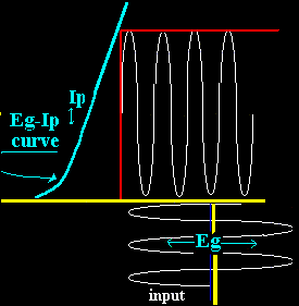 The reason for the output being a clean, non-distorted copy of the input, has to do with the biasing of the amplifier. By putting the average input bias point (represented by voltage Eg in the diagram) dead center of the amplifier's gain curve, we set the amplifier up for maximum fidelity - true reproduction of the input signal. Distortion takes place, when the applied signal's highs and lows go beyond the capability of the active device (the tube or transistor), and the active device either goes into cutoff or saturation. In a class A device, we would alwlays set the operating point directly in the center of it's operating curve, such that the highs and lows would not go beyond the cutoff or saturation points of the active device.
Amplifier circuits are not always designed to generate a perfectly pure signal. Sometimes they are SUPPOSED to introduce distortion for one reason or another. These circuits are classified as classes B, AB and C for analog designs, and classes D and E/F for switching designs. Below are brief descriptions of all the amplifier classes. Class A - 100% of the input signal is used (conduction angle Θ= 360° or 2π) Class A amplifiers amplify over the entire input cycle such that the output signal is an exact magnified copy of the input. They are not efficient (no more than 50% efficiency is attainable), since the amplifying device is always conducting whether or not an input signal is applied. Class B - 50% of the input signal is used (Θ= 180° or π) 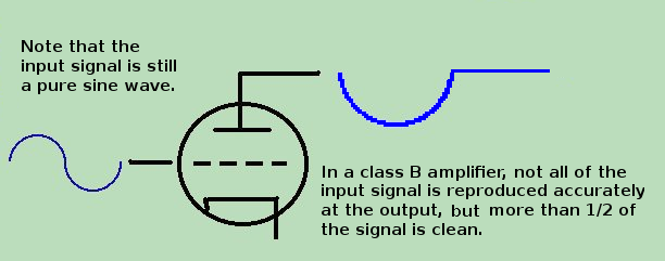  A Class B amplifier has an operating point set at one extreme end of its characteristic, so that either the quiescent current or the quiescent voltage is almost zero. If a sine wave is applied to the input, the amplification takes place only for 50% of the whole cycle. In other words, the amplifying device is switched off half of the time. This is done by applying quiescent bias voltage to the active device such that its characteristic curve runs either in saturation or cutoff 50% of the time. It is possible for a Class B amplifier to obtain efficiency of up to 78.5%. This is because it is turned off at least 50% of the time. Because they run in saturation or cuttoff, Class B amplifiers exhibits a high amount of distortion. Because they generate distortion - they are normally not used in audio or video circuits - unless of course distortion is desired (like on an electric guitar). Of special note is the fact that the output of a Class B amplifier closely resembles the output of an ordinary diode (possible hint to future designers).
Class AB - more than 50% but less than 100% is used. (Θ= 181° to 359°, π < Θ < 2π) 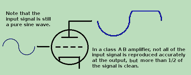
A Class AB amplifier is an amplifier that operates between the two extremes defined for Class A and B amplifiers. Class C - less than 50% is used (0° to 179°, Θ < π) 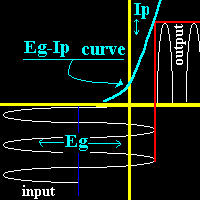 Class C amplifiers conduct less than 50% of the input signal, allowing it to reach 90% efficiency but resulting in high distortion at the output. Thus, in a Class C amp, the output current (or voltage) is zero for more than 50% of the input waveform cycle. Some applications, such as megaphones, can tolerate the high distortion of Class C amps. Class C amps can also be used in tuned RF applications, since the distortion can be significantly reduced by the tuned loads.
Class D A class D amplifier is a power amplifier whose power devices are operated in on/off mode. The input signal is converted into a sequence of pulses whose peak is directly proportional to the average amplitude of the input signal. The frequency of the pulses is typically ten or more times the highest frequency of interest in the input signal. The output of the amplifier must then go through a passive filter to remove any unwanted spectral components, resulting in an amplified replica of the input. Power efficiency and fast switching are the main advantages of a class D amplifier. Class D amplifiers were widely used to control motors, low frequency power amplifiers (think woofers in audio), or on occasion in A/D converters. Class E/F Class E/F amplifiers are special cases. They are extremely low power usage switching amplifiers used typically only for radio frequencies. Class E/F amplifiers consist of two basic parts:
|
| (On The Following Indicator... PURPLE will indicate your current location) | ||||||||||||||||||||||||
| 1 | 2 | 3 | 4 | 5 | 6 | 7 | 8 | 9 | 10 | 11 | 12 | 13 | 14 | 15 | 16 | 17 | 18 | 19 | 20 | 21 | 22 | 23 | 24 | 25 |
| 26 | 27 | 28 | 29 | 30 | 31 | 32 | 33 | 34 | 35 | 36 | 37 | 38 | 39 | 40 | 41 | 42 | 43 | 44 | 45 | 46 | 47 | 48 | 49 | 50 |
| 51 | 52 | 53 | 54 | 55 | 56 | 57 | 58 | 59 | 60 | 61 | 62 | 63 | 64 | 65 | 66 | 67 | 68 | 69 | 70 | 71 | 72 | 73 | 74 | 75 |
[COURSE INDEX] [ELECTRONICS GLOSSARY] [HOME]
| Otherwise - please click to visit an advertiser so they know you saw their ad! |
