

A C Theory Earlier we discussed that there are various ways to produce electricity. We
can produce electricity chemically with a battery. We just learned that
electricity can be produced mechanically by a generator. What we did not
discuss in detail, though, was the difference between electricity produced by a
battery, and electricity produced by a generator.
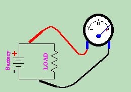
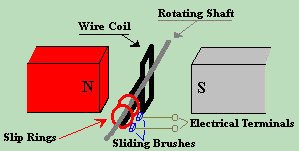
In the case of a battery, electricity flows in one direction, from positive to negative. Everything is straightforward. In the case of a generator, however, things get a bit more complicated.  It is possible to generate electricity by spinning a coil within a magnetic
field. The coil is in constant motion within the magnetic field, and thus is
transformed into electricity via the magnets. The electricity exits by way of
the brushes and slip rings, but it is not exactly like the electricity which is
produced by a battery.
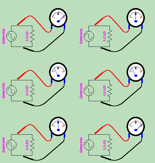
If we look at the current leaving the battery, it is constantly moving in the same direction. We call this DIRECT CURRENT . But if we attach a generator instead of a battery in the same circuit, we notice a major change. The meter would swing back and forth from negative to positive. This seems strange until we examine what is going on inside the generator. 
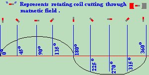
 However as the coil begins to turn, one side of the coil moves toward the north
pole. This end of the wire would become positive. At the same time, the other
side of the coil moves toward the south pole. This side of the coil becomes
negative. At this time, current begins to flow from the positive to the
negative. Current continues to flow in this direction and reaches a peak in
its cycle. This Maximum amount of current flow is reached when the coil is
pointing exactly north and south. We call this the 90
o
point, and say that the signal has reached its positive peak. After it
passes this point, the voltage begins to drop, but doesn't reach 0 until once
again the coil is positioned directly between the permanent magnets. This is
the 180
o
point.
Now comes the switch up. As the coil continues to turn, the end that was positive now moves toward the south pole of the magnet. Because it is passing by the south pole, this end of the coil swings negative. At the same time, the side of the coil that was negative, is now swinging positive. Thus, the direction of current flow within the wire is switched. The current flow continues in this direction until it again reaches a (this time negative) peak at 270 o . Finally, as the coil approaches its original position, it swings positive until current flow again reaches 0. By graphing the current vs. time, we end up with a pattern known as a SINUSOIDAL WAVE , or SINE WAVE for short. We say that the sine wave has positive and negative peeks at 90 o and 270 o respectively. |
| (On The Following Indicator... PURPLE will indicate your current location) | ||||||||||||||||||||||||
| 1 | 2 | 3 | 4 | 5 | 6 | 7 | 8 | 9 | 10 | 11 | 12 | 13 | 14 | 15 | 16 | 17 | 18 | 19 | 20 | 21 | 22 | 23 | 24 | 25 |
| 26 | 27 | 28 | 29 | 30 | 31 | 32 | 33 | 34 | 35 | 36 | 37 | 38 | 39 | 40 | 41 | 42 | 43 | 44 | 45 | 46 | 47 | 48 | 49 | 50 |
| 51 | 52 | 53 | 54 | 55 | 56 | 57 | 58 | 59 | 60 | 61 | 62 | 63 | 64 | 65 | 66 | 67 | 68 | 69 | 70 | 71 | 72 | 73 | 74 | 75 |
| Otherwise - please click to visit an advertiser so they know you saw their ad! |
