

Other Types of Meters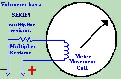 Or what if you wanted to know the amount of current flowing through a circuit,
so that you knew what size of fuse to put in the circuit? You would need an
Ammeter to measure the current in Amps.
Or what if you wanted to know the amount of current flowing through a circuit,
so that you knew what size of fuse to put in the circuit? You would need an
Ammeter to measure the current in Amps.
Recall that the Voltmeter had a resistor in series with it. This resistor, called the "Multiplier Resistor" was used to calibrate the meter to work within a given range. A Voltmeter is also placed in parallel with the circuit in test. 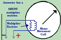 An Ammeter, on the other hand, is built with a resistor in PARALLEL or in SHUNT
with the D'Arsonval movement's coil. In the case of the Ammeter, the SHUNT
resistor is of a very low resistance. Much lower resistance, in fact, than the
coil in the meter movement. Remember finding resistance in a parallel circuit?
The two resistors in parallel carry more current than either of the resistors
by themselves. This is because the combined resistance is lower than the
lowest resistor in the parallel network. Also, the resistor with the lowest
resistance always carries the greatest current. This is of utmost importance
here. If too much current were to go through our sensitive meter coil, it
would burn up and destroy the coil, hence making the meter useless. The
answer, of course, is to make sure that no matter HOW high the current, the
majority of the current will always flow through the shunt resistor. It is for
this reason that the shunt resistor has a lower resistance value than the coil
winding of the meter itself. The formula we use for finding the value of the
shunt resistor is as follows:
An Ammeter, on the other hand, is built with a resistor in PARALLEL or in SHUNT
with the D'Arsonval movement's coil. In the case of the Ammeter, the SHUNT
resistor is of a very low resistance. Much lower resistance, in fact, than the
coil in the meter movement. Remember finding resistance in a parallel circuit?
The two resistors in parallel carry more current than either of the resistors
by themselves. This is because the combined resistance is lower than the
lowest resistor in the parallel network. Also, the resistor with the lowest
resistance always carries the greatest current. This is of utmost importance
here. If too much current were to go through our sensitive meter coil, it
would burn up and destroy the coil, hence making the meter useless. The
answer, of course, is to make sure that no matter HOW high the current, the
majority of the current will always flow through the shunt resistor. It is for
this reason that the shunt resistor has a lower resistance value than the coil
winding of the meter itself. The formula we use for finding the value of the
shunt resistor is as follows:
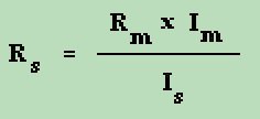
R m = meter movement resistance I m = full scale meter movement current I s = shunt current 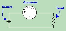 The Ammeter, unlike the Voltmeter, is not used in parallel with the circuit in
test. Rather, the ammeter is placed in series with the circuit - essentially
becoming an integral part of the circuit in test. If a Voltmeter were to be
removed from a circuit in test, the circuit would continue to run. If an
Ammeter were to be removed while the circuit were running, the circuit would
shut down, because there would no longer be continuity or flow of electricity.
The Ammeter, unlike the Voltmeter, is not used in parallel with the circuit in
test. Rather, the ammeter is placed in series with the circuit - essentially
becoming an integral part of the circuit in test. If a Voltmeter were to be
removed from a circuit in test, the circuit would continue to run. If an
Ammeter were to be removed while the circuit were running, the circuit would
shut down, because there would no longer be continuity or flow of electricity.
Finally, the Ohmmeter is one of the most used tools on the electronics workbench. It is used not only to measure the resistance value of a given resistor or circuit component, but also to check continuity of wire, to test for opens and shorts in a circuit, and many other things. But an ohmmeter is not self sufficient. 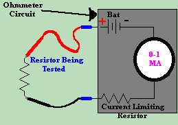
|
| (On The Following Indicator... PURPLE will indicate your current location) | ||||||||||||||||||||||||
| 1 | 2 | 3 | 4 | 5 | 6 | 7 | 8 | 9 | 10 | 11 | 12 | 13 | 14 | 15 | 16 | 17 | 18 | 19 | 20 | 21 | 22 | 23 | 24 | 25 |
| 26 | 27 | 28 | 29 | 30 | 31 | 32 | 33 | 34 | 35 | 36 | 37 | 38 | 39 | 40 | 41 | 42 | 43 | 44 | 45 | 46 | 47 | 48 | 49 | 50 |
| 51 | 52 | 53 | 54 | 55 | 56 | 57 | 58 | 59 | 60 | 61 | 62 | 63 | 64 | 65 | 66 | 67 | 68 | 69 | 70 | 71 | 72 | 73 | 74 | 75 |
| Otherwise - please click to visit an advertiser so they know you saw their ad! |
