

Lesson 50 - Power SuppliesThis is a great way to get power into the homes of everyone on the planet. The big problem comes in that most electronic circuits don't normally work on AC - they work on DC. So we need some way to convert an Alternating Current power service, into Direct Current for your equipment and devices to run off. Fortunately, this has been taken care of in most of your equipment. Most modern electronics equipment has a power supply built in. That power supply takes the AC line voltage coming into your home, and converts it into the needed DC voltages that your equipment uses. You as an electronic technician or engineer are expected to be able to design and/or repair these power supplies. It would behoove you, therefore, to learn how the work, no? Basic power supplies can normally be divided into 4 parts:
The purpose of the transformer is twofold: First, it will ISOLATE the equipment after the transformer from the main power source coming into the transformer. Because the neutral wire of an electrical outlet is directly connected to ground, any grounded objects near your piece of equipment (lamp, toaster, DVD player, concrete floor, etc.) may be at a hazardous potential difference with respect to that piece of equipment. Because the transformer "isolates" the equipment electrically, the physical connection is eliminated, and the shock hazard between those two devices negated. 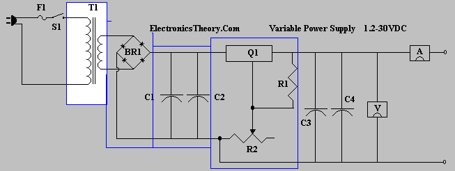
Second, it is used to step up or down the voltage ( or voltages ) to those required within your device. The Rectifier: As we've already discussed, a rectifier changes AC to DC. This can be accomplished with either tube or semiconductor diodes. There are different types of rectification circuits, most predominantly half and full wave, but they all perform the same basic function. Some are simply more efficient at the job. As discussed before, the DC voltage that they produce isn't exactly the same as the DC voltage provided from a battery. If we were to look at the output of the DC provided by a battery on an oscilloscope, it would simply look like straight, flat, horizontal line. If on the other hand, we look at the DC output of a transformer, it looks more like a bunch of camel humps. That is because while ALL of the voltage coming out of the rectifier is of the same polarity, it is still ALTERNATING from 0 volts to whatever the peak voltage is, then back down to zero. We can certainly take that voltage and make it look more like the DC voltage coming out of a battery, but this is done using a FILTER circuit. 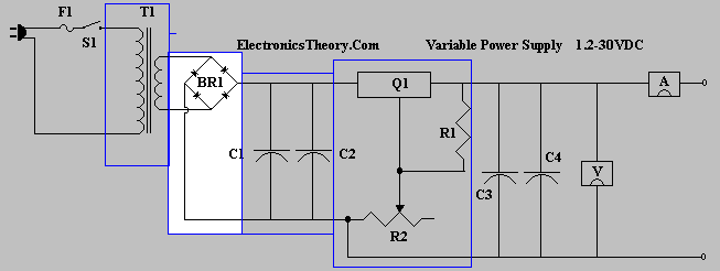
The Filter: The filter in a power supply takes the raw "alternating" DC humps that come out of the rectifier, and smooths them out. Almost always this is done by capacitive means, with the capacitor being placed in parallel with the rectifier and load, but quite often, a coil (or two) may also be placed in series with the power. The capacitor takes the alternating portion of the DC, and passes it to ground, neutralizing it. Note that it passes the effects of the AC, but BLOCKS the DC component of the power, allowing it to stay where it is. If a coil is used, it will pass the DC component of the power to other components in series with it, while blocking the effects of AC from getting to later components. 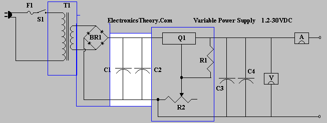
The Regulator: While not all equipment has a regulator, it is not a bad design feature, and if it can be economically added, it should be. The purpose of the regulator is to compensate for fluxuations in incoming voltage, and keep the outgoing voltage at a steady level. This protects other components from early failure, as well as providing better stability and operation of the circuit. 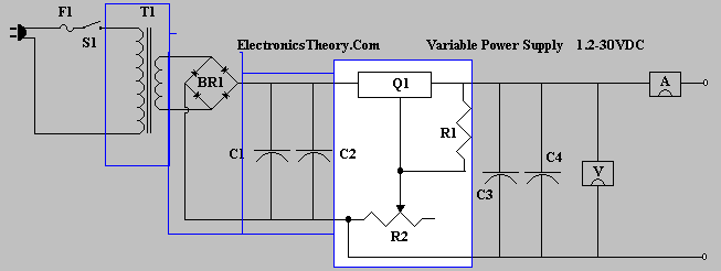
Now that you understand the basic parts of the power supply - let's build one - either virtually, or actually - your choice! Here is a complete schematic of a working power supply. Note that if you build this power supply, it can be a useful tool in your arsenal of test equipment, and can be a building block and test lab for later projects you might choose to build. This particular design produces a well filtered, variable voltage from 1.2-30 Volts DC @ 5 amps. It is easy to build, and the parts are easy to find. 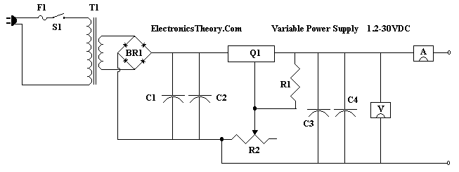
This power supply brings power in from the "hot" side of the power plug, through a series connected fuse, a power switch, into the input of a transformer, and finally back out the neutral side of the power plug. Because it is a series circuit, if the switch is open, no current flows, and the power is off. Also, should something go wrong, (assume you spill your soda on the power supply while it's running), the fuse will open and protect you from all harm, because the fuse is also in series, and will not allow current to flow at all in the circuit if it opens. The transformer (T1) is a step down transformer, with 120 Volts in, and 24 Volts @ 5 Amps output. This of course, will provide the voltages for the rest of the circuit, while also isolating you from the incoming line voltages. The higher the current rating the more projects you'll be able to work with in the future. I prefer something akin to a Triad F-260U, which is still available at MOUSER for about $40 American. You could just as easily salvage a good one from an old TV set at a junk yard - if you can find one with the right voltage output, or settle for a smaller transformer, but the current rating would be lower. Next comes a FULL WAVE BRIDGE rectifier (BR1). This is called a full wave, because it rectifies BOTH sides of the AC signal, utilizing 4 diodes. In this particular device, all 4 diodes are included in 1 package - a 10 Amp 50 Peak Inverse Voltage Bridge Rectifier package NTE53000 thru NTE53004 would work fine. The Filter, in this case, is a combination of 2 capacitors. The first (C1) is a 14000uF (microFarad) 40VDC Electrolytic Capacitor. The second (C2) is a 100uF/50V Electrolytic Capacitor. Finally, (Q1), is an LM338 Regulator. Basically, it is a 3 legged device, like a transistor, that is used to regulate the voltage, and control the output voltage. R1 is a 240 Ohm, 1/4 Watt bias resistor, and R2 is a 5K Ohm Variable Resistor, for setting the output voltage level. For further stabilization and protection of Q1, two more capicitors (C3 - .1uF Disc Capacitor) and (C4 - .02uF Disk Capacitor) are included. Note that Q1 comes in a "TO-3" case, and generates a lot of heat. It MUST be provided a large heatsink, and possibly a fan to keep it cool. The Volt and Ammeters included in the diagram are not necessary, but are a nice feature to add, should you want to make a very nice power supply. Parts List:
|
| (On The Following Indicator... PURPLE will indicate your current location) | ||||||||||||||||||||||||
| 1 | 2 | 3 | 4 | 5 | 6 | 7 | 8 | 9 | 10 | 11 | 12 | 13 | 14 | 15 | 16 | 17 | 18 | 19 | 20 | 21 | 22 | 23 | 24 | 25 |
| 26 | 27 | 28 | 29 | 30 | 31 | 32 | 33 | 34 | 35 | 36 | 37 | 38 | 39 | 40 | 41 | 42 | 43 | 44 | 45 | 46 | 47 | 48 | 49 | 50 |
| 51 | 52 | 53 | 54 | 55 | 56 | 57 | 58 | 59 | 60 | 61 | 62 | 63 | 64 | 65 | 66 | 67 | 68 | 69 | 70 | 71 | 72 | 73 | 74 | 75 |
| Otherwise - please click to visit an advertiser so they know you saw their ad! |
